Tax-inclusive reference prices in CNY. Negotiable; the quotation reflects the selected configuration, quantity and delivery requirements. All products carry a 3-year warranty.
For a complete system, include the power supply, sensors, communication access and platform deployment in your enquiry.
At a glance
Axes8 STEP/DIR/EN groups
LimitsUpper and lower limits per axis
STEP requestsUp to 100kHz per axis
Trajectory sliceNormally 4ms
Product overview
The card provides independent axis commands, synchronized starts and trajectory execution for pulse-and-direction drives. Drivers, motors, limits and independent stopping circuits complete the system; commanded and actual mechanical positions remain distinct.
Functions and integration
Axis commands
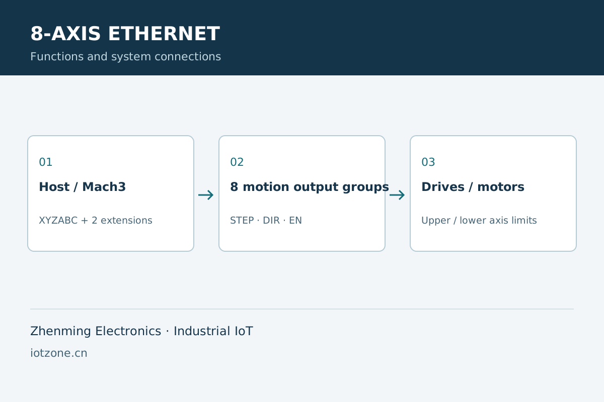
Each axis has STEP, DIR, EN and upper/lower limits, with finite pulse motion, acceleration, deceleration, stopping and disable.
Synchronized execution
Prepare multiple axes and start them together. Host software generates line, arc and curve trajectories for queued execution, normally in 4ms slices.
Mach3 and management
Mach3 R3.041 Win32 provides XYZABC plus two physical expansion axes. Browser management covers status, manual operations, parameters and logs.
Electrical and position model
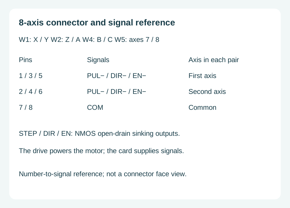
External STEP/DIR/EN outputs use NMOS open-drain sinking. Reported position is commanded pulse position, not measured motor position.
Applications and operating workflow
Multi-axis equipment
Organize independent and synchronized actions for suitable pulse-direction drives.
Commissioning
Establish direction, enable and limit behavior before configuring host trajectories.
Maintenance
Use timestamped logs and exports while retaining independent hardware stopping circuits.
Technical data and interfaces
Axes
8 STEP/DIR/EN groups
Limits
Upper and lower limits per axis
STEP requests
Up to 100kHz per axis
Trajectory slice
Normally 4ms
Mach3
R3.041 Win32; XYZABC plus two expansion axes
Management
Ethernet Web, UART commands and Mach3 plugin
Position
Commanded position, not encoder feedback
Axis connectors
W1: X/Y; W2: Z/A; W4: B/C; W5: physical axes 7/8
Maintenance UART
3.3V TTL; 115200 bit/s; 8N1
External limit polarity
Active low
SNMP versions (Ethernet)
v1/v2/v3
Optional Ethernet protocols
BACnet/IP, EtherNet/IP (optional)
Selection and system combinations
Plan motion control around axes, drives and control software. Ordinary relay switching and pulse measurement remain separate duties for the respective controllers and acquisition devices.
Select for DC motor direction and linear-actuator travel requirements. Multi-axis motion and ordinary circuit switching are different tasks; relay count alone does not define motion-control capability.
Separate frequency, duty-cycle and pulse-count requirements for periodic and counting signals. Voltage waveform acquisition and equipment contact-state acquisition use their respective modules.
The card organizes STEP, DIR and EN signals, the drive supplies motor power and the limits define travel conditions. Configure pulses per unit, velocity and acceleration from the transmission mechanics, then relate commanded position to physical position. The displayed position comes from commanded pulses; homing, limits and machine feedback support coordinate management.
02
Distinguish simultaneous starts from coordinated trajectories
Axes can execute finite-pulse moves independently or be prepared for a simultaneous start. Lines, arcs and curves require coordinated trajectories from the host for queued execution on the card; starting together alone does not establish geometric interpolation. Normal trajectories use 4ms slices. Assess completion from the queue, running state and machine state for test benches and equipment integration.
03
Integrate native Mach3 axes and the two expansion axes
The matching plugin connects Mach3 R3.041 Win32 to its native XYZABC axes. Physical axes 7 and 8 use the supplied interface or macros for auxiliary feeding, fixtures or independent actions. Browser functions cover status, manual motion, parameters and logs, while UART provides command access. Use one motion-control source at a time and finish its session and trajectory before switching sources.
04
Map connector pairs to the corresponding drives
W1 serves X/Y, W2 Z/A, W4 B/C and W5 physical axes 7/8. On each connector, pins 1, 3 and 5 carry the first axis PUL−, DIR− and EN−; pins 2, 4 and 6 carry the second axis signals, with COM on pins 7 and 8. External STEP, DIR and EN outputs use NMOS open-drain sinking. Match common-anode wiring to the drive input specification; the card does not provide motor power drive.
Keep limit inputs and maintenance UART electrically distinct
External limit terminals are active low; the logic-side polarity after optocoupling differs from the field terminal. Upper and lower limits remain distinct for each axis and correspond to the relevant motion direction. The maintenance UART uses 3.3V TTL at 115200 bit/s, 8N1, rather than RS232 voltage levels. Coordinate browser, UART and Mach3 access through the appropriate control session to prevent competing motion commands.
06
Convert motor pulses into distance or angle
Pulses per millimetre depend on motor steps per revolution, drive microstepping, transmission ratio and screw lead. For example, 200 steps per revolution, 16 microsteps and a directly driven 10 mm lead screw give 320 pulses/mm; these are example mechanical settings. Rotary axes convert pulses per revolution into pulses per degree. Relate a short commanded move to actual travel before applying the same conversion to travel, speed and software limits.
07
Distinguish stopping, disabling and position recovery
A decelerated stop acts on selected axes. Quick stop or disable stops and disables the corresponding axes; a global emergency stop applies to all axes. Browser, UART and Mach3 share the device motion state, so finish the active task and clear queued trajectories before changing the control source. Displayed position comes from commanded pulses. Recheck physical position after power loss, missed steps or faults and home as required.
08
Ethernet protocols and system integration
Ethernet controllers support SNMP v1/v2/v3; BACnet/IP and EtherNet/IP are optional protocol capabilities for project integration.
Selection questions
Does starting axes together generate a line or arc?
A simultaneous start aligns start times. Lines, arcs and curves require coordinated trajectories generated by the host and executed through the trajectory queue and time slices.
How do the browser and Mach3 divide responsibilities?
The browser provides state viewing, manual operation, parameters and logs. The matching Mach3 plugin supplies program trajectories. Finish the active motion session before changing control sources.
Is displayed pulse position the actual motor position?
The display reports commanded pulse position. The card does not read actual motor position; use homing, limits and machine feedback to manage physical coordinates.
How are millimetres converted to pulses?
Pulses per millimetre equal motor full steps per revolution multiplied by microsteps and transmission ratio, divided by screw travel per revolution. Rotary axes use pulses per revolution to convert angle.
Which SNMP versions are supported, and are BACnet/IP and EtherNet/IP optional?
Ethernet controllers support SNMP v1/v2/v3; BACnet/IP and EtherNet/IP are optional protocol capabilities for project integration.
Frequently asked questions
Are all eight axes native Mach3 axes?
Mach3 uses native XYZABC axes; physical axes 7 and 8 are expansion axes.
Is encoder feedback provided?
This configuration tracks commanded pulses rather than measured motor position.